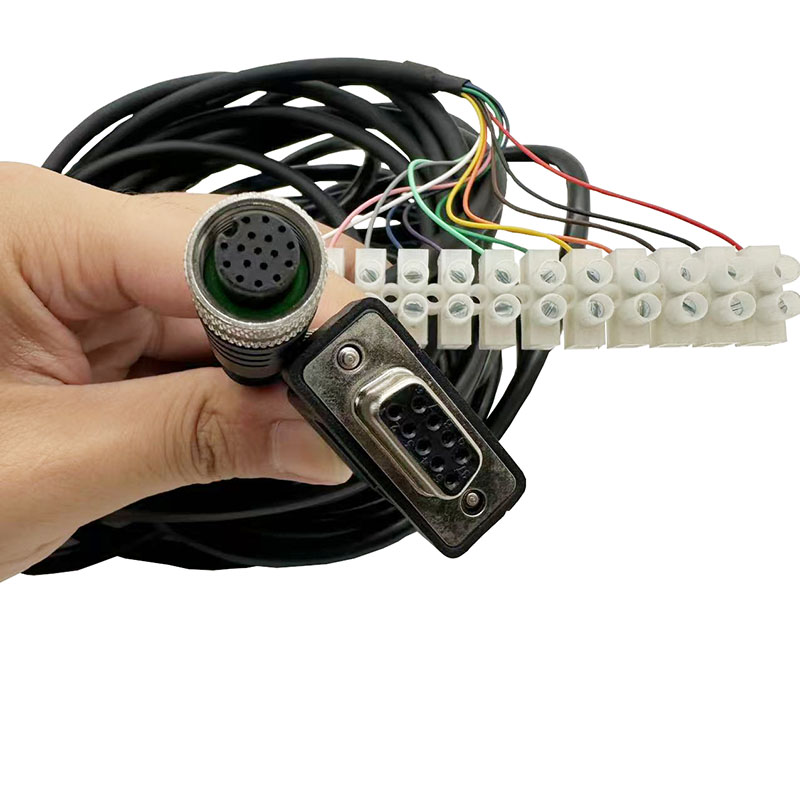
Automotive electrical failures often present as phantom issues that resist standard troubleshooting. Vehicle owners and fleet managers struggle to differentiate between a localized electrical fault and systemic degradation. A localized issue might just need a simple splice or a new pigtail connector. Systemic degradation usually necessitates a complete replacement. Misdiagnosing this fundamental difference leads to compounded labor hours, recurring breakdowns, and severe fire risks. You need an evidence-based diagnostic framework to identify definitive signs of electrical failure. This guide helps you evaluate the repair-versus-replace threshold and mitigate risks during implementation. By understanding how to trace symptoms back to their source, you can stop chasing electrical gremlins and restore reliable vehicle operation. We will cover physical inspections, multimeter testing, and specific failure points across different vehicle platforms to keep your equipment running.
Systemic vs. Localized Symptoms: Isolated accessory failures often point to localized faults, while cascading electrical issues, persistent ECU errors, and recurring blown fuses indicate systemic harness degradation.
Physical Evidence is Definitive: Frayed wires, melted insulation, brittle casings, and pervasive green copper corrosion (verdigris) dictate immediate replacement over patching.
The Labor Cost Reality: In many cases, the diagnostic labor hours required to trace and repair multiple shorts exceed the cost of dropping in a new automotive wiring harness.
Application-Specific Risks: An engine wiring harness faces extreme thermal cycling, while a motorcycle wiring harness is highly susceptible to UV degradation and moisture intrusion, altering the expected lifespan of each.
Understanding the Architecture of an Automotive Wiring Harness
Establishing a baseline understanding of power distribution is mandatory before you start cutting wires or replacing parts. You cannot accurately trace symptoms to their source without knowing how the electrical system routes power and data. The automotive wiring harness acts as the central nervous system of the vehicle. It connects the battery, alternator, Engine Control Unit (ECU), body control modules, and all peripheral components into a unified network. Modern vehicles do not just send 12 volts to a lightbulb; they send low-voltage data signals to modules that then command the lightbulb to turn on.
The Network of Arteries and Data Lines
Modern vehicles rely heavily on complex data networks alongside traditional 12-volt power delivery. The Controller Area Network (CAN) bus allows microcontrollers and devices to communicate without a host computer. These data lines transmit high-speed square wave signals that control everything from fuel injection timing to anti-lock braking systems. When a wire degrades, it does not just stop power flow. It alters the electrical resistance of the circuit. This altered resistance corrupts the data packets traveling along the CAN bus. A corrupted data packet can cause the transmission to shift erratically or the dashboard to light up with communication error codes (U-codes).
Standardized Color Coding and Circuit Identification
Manufacturers utilize specific wire color functions to streamline tracing and aftermarket integration. While exact colors vary by manufacturer and region, universal aftermarket standards often apply to simplify repairs. Understanding these color codes allows technicians to isolate specific circuits quickly. If a yellow wire shows high resistance, you immediately know to focus your diagnostics on the signaling circuit rather than the main power distribution block.
Wire Color (Typical Aftermarket)
Primary Function
Common Diagnostic Focus
Red
Constant 12V Battery Power
Main fuses, fusible links, battery terminals
Black
Chassis Ground
Corroded ring terminals, loose bolts on bare metal
Yellow
Switched Ignition Power / Signals
Ignition switch contacts, turn signal relays
White / Gray
Lighting / Illumination
Headlight switches, dimmer modules
Twisted Pair (Various)
CAN Bus Data Lines
Module connectors, terminating resistors
Sub-Harness Segmentation
Vehicles do not use a single, continuous loop of wire. The system is segmented into multiple sub-harnesses connected by bulkheads and multi-pin connectors. The main chassis harness runs the length of the vehicle, powering taillights, fuel pumps, and interior accessories. The engine loom manages ignition coils, fuel injectors, and critical sensors. Accessory looms handle doors, seats, and infotainment systems. Segmenting your troubleshooting efforts by isolating these sub-harnesses prevents you from tearing apart the interior when the fault actually lies under the hood. For example, a short in the driver's door harness where it flexes in the door jamb can blow a fuse that also powers the dashboard cluster. Unplugging the door sub-harness isolates the short immediately.
Definitive Signs You Need a Wiring Harness Replacement
Recognizing the difference between a failing component and a failing wiring harness saves countless hours of misdirected labor. Electrical faults rarely heal themselves. They progressively worsen as heat, vibration, and moisture take their toll on compromised copper.
Erratic and Cascading Electrical Failures
Isolated failures usually point to a bad relay, a blown fuse, or a dead component. Cascading failures point directly to the wiring loom. You might notice multiple unrelated accessories failing simultaneously. Headlights might dim when you press the brake pedal. The radio might cut out completely when you drive over a bump. Power windows might operate sluggishly while the dashboard lights flicker. These symptoms indicate a shared ground failure or a dead short where multiple circuits are bleeding voltage into one another. When a main ground strap corrodes, the electrical current seeks an alternative path back to the battery, often traveling through thinner wires or shifter cables, causing bizarre, cascading symptoms.
Persistent Check Engine Lights and Sensor Faults
Degraded wiring alters circuit resistance. The ECU relies on precise voltage returns from sensors to manage engine timing and fuel delivery. A common 5-volt reference circuit powers multiple sensors, such as the Manifold Absolute Pressure (MAP) sensor, Throttle Position Sensor (TPS), and AC pressure switch. If the insulation on that circuit chafes and touches bare metal, it drags the entire 5-volt reference down to zero. The ECU will then throw false codes for all those sensors simultaneously. Replacing the sensors will not fix the problem. The underlying issue is the compromised copper altering the voltage before it ever reaches the ECU.
Physical Degradation and Fluid Intrusion
Visual inspection often provides the most definitive evidence. Look for frayed wires near moving suspension parts. Inspect the insulation for brittleness or deep cracks. When plastic insulation ages and faces constant thermal cycling, it hardens and flakes off, exposing bare copper. Check for chafing where the loom routes over sharp metal edges or passes through firewall grommets. Fluid intrusion is another major killer. Engine oil or power steering fluid leaking onto a harness will degrade the plastic insulation over time, turning it into a sticky, melted mess. Furthermore, oil can wick up the inside of the wire casing through capillary action, traveling from a leaking sensor all the way into the ECU connector, destroying the computer.
Recurring Blown Fuses and Parasitic Draws
A fuse is designed to protect the circuit from overcurrent. If you replace a blown fuse and it immediately pops again upon turning the key, you have a dead short to ground. The current is bypassing the intended load and flowing directly into the chassis. Parasitic draws occur when a circuit fails to power down after the ignition is turned off. A shorted wire can bypass the ignition switch entirely, keeping modules awake and draining the battery overnight. Continually replacing batteries or fuses treats the symptom, not the root cause. You must trace the circuit to find where the insulation has failed.
Burning Odors and Smoke
Electrical fires present immediate safety risks. An acrid, burning plastic smell is often the first warning sign of an impending thermal event. When a wire carries more amperage than its gauge can handle, it acts like a toaster heating element. The copper glows red hot, melting the surrounding insulation and igniting nearby plastics. Any thermal event within the loom mandates a full replacement. Localized repair is unsafe because the excessive heat travels up the copper wire, annealing the metal and destroying the insulation far beyond the visible burn mark.
Diagnostic Framework: Testing the Wiring Harness
Moving beyond visual inspection requires quantifiable electrical testing. Guesswork leads to replacing functional parts. A structured diagnostic approach eliminates the frustration of chasing phantom faults. You need a high-quality digital multimeter, back-probe pins, and a solid understanding of Ohm's law.
Multimeter and Oscilloscope Testing
Continuity testing only tells you if a wire is broken. It does not tell you if the wire can carry a load. A single strand of copper will test positive for continuity but will fail instantly under a 10-amp load. You must perform a voltage drop test to evaluate the health of the copper.
Set your digital multimeter to the DC volts scale.
Turn on the circuit you want to test so current is flowing.
Place the positive multimeter lead on the battery positive post.
Place the negative multimeter lead on the positive terminal of the component you are testing (e.g., the power wire at the headlight bulb).
Read the voltage on the screen. A reading higher than 0.5 volts indicates excessive resistance within the loom, meaning the wire is corroded or damaged.
Repeat the process on the ground side, placing one lead on the component ground and the other on the negative battery post.
For high-speed data lines, a multimeter is too slow. An oscilloscope is required to view the square wave patterns of the CAN bus. Corrupted, rounded-off waveforms indicate compromised twisted-pair wiring or a failed terminating resistor.
Wiggle Testing with Live Data
Intermittent breaks inside intact insulation are notoriously hard to find. The copper strands break internally, but the plastic casing holds them together. Vibration causes them to connect and disconnect rapidly. Connect an OBD-II scanner and pull up live data for the suspect circuit. While monitoring the data stream, physically grasp the loom and aggressively wiggle it at various flex points, connectors, and bulkheads. If the live data spikes or drops out during the wiggle test, you have pinpointed the exact location of the internal break.
Application-Specific Diagnostics
Different vehicles expose their electrical systems to different environmental stressors. Diagnostics must adapt to these specific conditions.
Engine Bay Focus: The engine wiring harness faces extreme heat, chemical exposure from oil leaks, and constant engine vibration. Focus your diagnostics on injector pigtails, coil pack connectors, and heat-soaked sensor wires near the exhaust block. Look for oil intrusion inside the connectors, which acts as an insulator and blocks the electrical connection. Diesel engines often suffer from chafing where the harness routes over the valve covers.
Two-Wheeled Focus: A motorcycle wiring harness is highly susceptible to UV degradation, direct rain, and tight turning radiuses. Inspect the steering neck pinch points where the loom flexes every time the handlebars turn. Check the main ground terminals bolted directly to the exposed frame, as these frequently corrode. Evaluate weather-pack connector seals for moisture intrusion, especially after pressure washing the bike.
The Repair vs. Replace Decision Matrix
Deciding whether to patch a damaged section or overhaul the entire system requires evaluating the extent of the damage, the type of circuit involved, and the long-term reliability required. A poor repair will leave you stranded on the side of the road.
When Localized Repair is Viable
Localized repairs are acceptable for isolated incidents. If a single wire breaks due to accidental mechanical damage, like a slipped wrench or a pinched wire during a transmission installation, you can repair it. The copper must be bright, shiny, and free of corrosion. Use uninsulated butt connectors, crimp them properly with a ratcheting crimper, and seal the repair with dual-wall, adhesive-lined heat shrink tubing. Solder sleeves are also highly effective for creating a waterproof, mechanically sound joint. Localized repairs are generally safe for simple 12-volt power or ground circuits that do not transmit high-speed data. Never use household wire nuts on a vehicle; vibration will back them off immediately.
When Full Replacement is Mandatory
Certain types of damage compromise the entire network, making patching impossible or highly unsafe.
Black Wire Disease: If you strip back the insulation and find black or green powdery copper, moisture has wicked up inside the wire casing. This corrosion increases resistance dramatically. You cannot solder oxidized copper. The corrosion often extends several feet up the loom, requiring full replacement.
Extensive Rodent Damage: Rodents chew through soy-based wire insulation, often damaging multiple branches of the loom in hard-to-reach areas like under the intake manifold. Patching 20 different wires in a tight space introduces too many potential failure points.
Compromised Data Lines: CAN bus networks rely on twisted pair wiring with specific resistance values, typically 60 ohms across the network. Splicing these lines alters the length and resistance, which can permanently disrupt module communication.
Flood Damage: Submersion forces water into every connector, and capillary action pulls it deep into the wire strands. The subsequent galvanic corrosion will cause endless, unpredictable electrical failures over the coming months.
Evaluating Labor Hours and Reliability
Consider the comparative labor hours. Tracing a complex short through a dashboard, removing interior panels, unwrapping factory tape, finding the break, repairing it, and reassembling the vehicle can easily take ten to fifteen hours of diagnostic labor. If the loom is old and brittle, fixing one wire often breaks another nearby. In many scenarios, the upfront parts and labor required to install a brand-new, factory-fresh loom is significantly lower than the ongoing labor hours spent repeatedly chasing electrical gremlins.
Symptom / Condition
Underlying Cause
Recommended Action
Single broken wire near a connector
Mechanical stress or accidental damage
Localized Repair (Pigtail replacement)
Green corrosion inside wire strands
Moisture intrusion and oxidation
Full Replacement
Melted insulation across multiple wires
Dead short to ground / Thermal event
Full Replacement
Rodent chewing on main trunk line
Pest damage to soy-based insulation
Full Replacement
Intermittent CAN bus communication errors
Altered resistance in twisted pair data lines
Full Replacement
Sourcing and Implementation Realities
Executing a replacement requires careful planning. Introducing a new loom into an older vehicle presents specific routing and grounding challenges that must be managed to ensure long-term reliability. Rushing the installation will introduce new faults before the vehicle even leaves the garage.
OEM vs. Aftermarket vs. Custom Built
Direct factory (OEM) replacements offer plug-and-play simplicity. The lengths, connectors, and mounting points match perfectly. However, OEM looms for older vehicles are often discontinued. Universal aftermarket kits provide a blank slate. They require you to terminate the ends and match their specific color codes to your vehicle's components. Custom-pinned harnesses are ideal for engine swaps or heavy restorations. They allow you to delete unused circuits, upgrade wire gauges for high-draw components like electric cooling fans, and utilize modern, waterproof connectors.
Routing and Strain Relief
Improper routing will destroy a new loom within months. You must follow the factory routing paths exactly. Utilize proper loom clips, zip-tie anchors, and edge protectors. Avoid high-heat areas like exhaust manifolds and EGR tubes. Ensure the loom has adequate slack where it crosses from the chassis to the engine block to accommodate engine torque movement. Tight routing creates pinch points that will eventually chafe through the new insulation. Always create a "drip loop" before a wire enters a connector pointing upward; this forces water to drip off the bottom of the loop rather than running down the wire directly into the connector seal.
Grounding Protocols
Ninety percent of post-installation electrical issues stem from improper grounding. A circuit is only as good as its ground path. If the ground is weak, current will seek alternative paths, often overloading thinner wires not rated for that amperage. Ensure all chassis grounds are attached to clean, bare metal. Remove any paint, rust, or powder coating under the ground ring terminal using a wire wheel or sandpaper. Use a star washer to bite into the metal, and apply dielectric grease over the bolted connection to prevent future oxidation. A dedicated ground strap from the engine block directly to the negative battery terminal is essential for proper starter and alternator function.
Conclusion
Take these actionable steps to address your electrical issues and restore vehicle reliability:
Perform a loaded voltage drop test on the main battery cables and primary alternator charge wire to rule out basic power supply issues.
Inspect the engine bay for chafed insulation near the exhaust manifold, steering shaft, and EGR routing.
Clean all primary chassis ground points down to bare metal, secure them with star washers, and apply dielectric grease.
Order a complete replacement loom if you discover green copper corrosion extending beyond the connector pigtails or if the vehicle has suffered flood damage.
FAQ
Q: Can a bad engine wiring harness cause a vehicle to stall while driving?
A: Yes. If the wires supplying power to the ignition coils, fuel injectors, or the main ECU short to ground or break internally due to vibration, the engine will immediately lose spark or fuel, resulting in a sudden stall while driving.
Q: Is it safe to drive a car with a damaged wiring harness?
A: No. Driving with damaged wiring poses a severe fire risk. Exposed copper can short against the chassis, creating intense heat that melts surrounding plastics and can ignite fuel vapors or interior materials. It also risks sudden loss of critical systems like headlights or power steering.
Q: How long does it take a mechanic to replace a main wiring harness?
A: Replacing a main chassis loom is highly labor-intensive. It typically requires removing the dashboard, seats, carpets, and interior trim panels. Depending on the vehicle's complexity, this process can take anywhere from 15 to 40 labor hours to complete properly.
Q: What are the most common causes of motorcycle wiring harness failure?
A: Motorcycles face harsh environmental exposure. The most common causes of failure include moisture intrusion leading to connector corrosion, UV degradation making wire insulation brittle, and physical chafing at the steering neck where the loom flexes constantly.
Q: Can you repair a melted or frayed wire harness, or does it need to be replaced?
A: A single frayed wire can be repaired with a solder sleeve or butt connector and heat shrink. However, if the loom is melted, the heat has likely fused multiple internal wires together and compromised the copper's integrity. Melted sections always require replacement.
Q: How do I know if my ECU is bad or if it is just the wiring harness?
A: You must test the inputs and outputs at the ECU connector using a multimeter or oscilloscope. If the ECU is receiving the correct voltage and sensor signals from the loom but fails to output the correct commands, the ECU is likely at fault. If the signals arriving at the ECU are already corrupted, the loom is the problem.