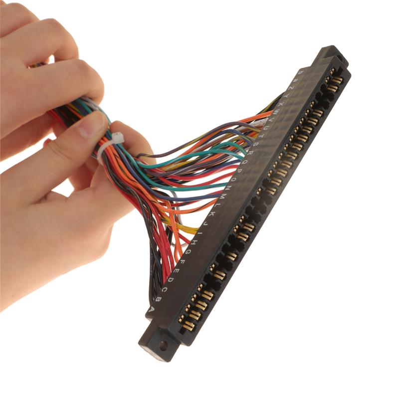
Electrical architecture drives the functionality of modern hardware. A single point of failure in a wiring harness compromises entire systems, causing equipment downtime or immediate safety hazards. Engineering and procurement teams face a continuous challenge on every project. You must balance strict technical specifications, regulatory compliance, and production efficiency when selecting a manufacturing partner. Navigating these requirements demands a clear understanding of the assembly floor.
Understanding the exact manufacturing workflow is essential for evaluating vendor capabilities. From digital design validation to final electrical testing and specialized packaging, every phase impacts the final product. Analyzing this step-by-step process helps you mitigate production risks, enforce quality control, and ensure the long-term reliability of your electrical systems.
Key Takeaways
Design for Manufacturability (DFM) is critical: Early engineering validation and ECAD/MCAD integration prevent costly mid-production revisions and ensure the custom wire harness meets application-specific tolerances.
Material selection dictates lifespan: Choosing the right insulators and conductors (e.g., high-temperature silicone) directly impacts performance in harsh environments.
Automation meets manual precision: While cutting and stripping are highly automated for consistency, complex routing and assembly still require skilled manual labor on specialized layout boards.
Testing is non-negotiable: Rigorous quality assurance, including pull testing and high-potential (Hi-Pot) testing, separates tier-one manufacturers from unreliable vendors.
Why the Manufacturing Process Matters for Procurement and Engineering
Defining Success Criteria
A successful production run extends far beyond meeting a delivery deadline. Engineering and procurement teams must define strict success criteria before the first wire is cut. Establishing these baselines prevents miscommunication and sets clear expectations for the manufacturing partner. The primary metrics for a successful run include:
Achieving a zero-defect rate on the final assembly line.
Maintaining absolute adherence to delivery schedules to prevent line-down situations.
Ensuring complete material traceability down to the individual terminal reel and wire spool.
Meeting exact dimensional tolerances during final routing and installation.
Traceability guarantees that every component can be tracked back to its original batch. If a connector manufacturer issues a recall, you can isolate the exact harnesses affected rather than scrapping your entire inventory.
The Cost of Poor Quality (COPQ)
Substandard manufacturing processes carry severe financial and reputational impacts. Consider the reality of a poorly calibrated crimping press. Inadequate crimping does not always fail immediately; it creates a high-resistance joint. Under load, this joint generates heat, melts the surrounding insulation, and eventually causes a dead short. The Cost of Poor Quality (COPQ) includes direct rework expenses, warranty claims, field technician dispatches, and irreversible brand damage. Investing in a manufacturer with a controlled, documented process eliminates these downstream liabilities.
Vendor Evaluation Lens
Transparency in a vendor's manufacturing process serves as a primary indicator of operational maturity. When a manufacturer openly shares their tooling calibration schedules, testing protocols, and layout board designs, they demonstrate a commitment to quality control. Evaluating these specific workflows allows procurement teams to separate capable manufacturing partners from brokers who simply outsource production to unverified facilities.
Step 1: Design Review, ECAD/MCAD Integration, and Engineering Validation
Receiving and Auditing Customer Files
The manufacturing process begins long before physical assembly. The initial phase involves receiving and auditing customer files. Engineers conduct a comprehensive review of STEP files, 2D electrical schematics, and the Bill of Materials (BOM) for the custom wire harness. This audit identifies obsolete components, missing dimensional tolerances, or conflicting pinout diagrams. Catching these discrepancies immediately prevents costly delays and material waste during physical assembly.
Digital Twin and ECAD/MCAD Co-Design
Modern manufacturers utilize advanced software to create a digital twin of the assembly. ECAD (Electrical Computer-Aided Design) and MCAD (Mechanical Computer-Aided Design) integration allows engineers to simulate spatial routing within the actual hardware enclosure. This digital validation verifies bend radii, calculates precise breakout lengths, and models thermal constraints. Simulating the physical environment ensures the harness will fit perfectly during final installation without excessive tension or slack.
Design for Manufacturability (DFM)
DFM analysis identifies potential bottlenecks before they reach the production floor. Engineers look for routing conflicts, connector crowding, or material incompatibilities. For example, specifying a massive bundle of rigid wires to pass through a narrow, high-vibration channel will fail in the field. DFM adjusts wire gauges, recommends alternative jacketing, and optimizes splice locations to streamline assembly and enhance field durability.
Prototyping and First Article Inspection (FAI)
Once the digital design is validated, the manufacturer builds the initial prototype. This physical build undergoes a First Article Inspection (FAI). The FAI verifies all physical dimensions, connector fits, and electrical performance metrics against the original specifications. Production does not scale until the engineering team approves the FAI report, establishing the baseline standard for the entire manufacturing run.
Step 2: Material Selection, Procurement, and Incoming Quality Control (IQC)
Conductor and Insulation Specifications
Selecting the correct raw materials dictates the operational lifespan of the assembly. Engineers evaluate wire gauges (AWG) based on current-carrying capacity and voltage drop requirements. Stranding types are selected based on flexibility needs; solid core wire suits stationary installations, while high-strand-count copper is mandatory for dynamic, moving environments. Insulation materials are chosen to resist specific threats, such as abrasion, moisture, or chemical exposure.
Common Insulation Materials and Field Applications
Insulation Material
Primary Characteristics
Typical Applications
PVC (Polyvinyl Chloride)
Cost-effective, good general abrasion resistance
Consumer electronics, standard automotive interiors
Teflon (PTFE)
Excellent chemical resistance, high temperature rating
Aerospace, medical devices, chemical processing
Silicone
Extreme flexibility, high thermal stability
Industrial robotics, high-heat engine bays
Cross-Linked Polyethylene (XLPE)
High dielectric strength, moisture resistant
Power distribution, heavy machinery
Specialized Environmental Considerations
Extreme environments require specialized insulation. When applications involve high heat, extreme cold, or continuous flexing, engineers often specify a silicone wire harness. Silicone maintains its flexibility at sub-zero temperatures and resists degradation in high-temperature industrial or automotive bays. Matching the insulation compound to the environmental hazard prevents premature jacket cracking and electrical shorts.
Connector and Terminal Sourcing
Connectors and terminals act as the interface points of the system. Manufacturers must source OEM-grade components from reputable brands like Molex, TE Connectivity, or Amphenol. Utilizing authentic components prevents mating failures, terminal push-out, and fretting corrosion. Strict supply chain management ensures that exact part numbers are procured, maintaining compliance with the original BOM.
Incoming Quality Control (IQC)
Procuring high-quality materials is only half the battle; verifying them is equally critical. Incoming Quality Control (IQC) is the strict inspection of raw materials upon arrival at the facility. Technicians verify copper purity, measure insulation thickness with micrometers, and inspect connector housings for molding defects. IQC mitigates the risk of counterfeit or substandard components entering the supply chain and compromising the final assembly.
Step 3: Automated Wire Cutting, Stripping, and Preparation
Precision Cutting
The physical transformation begins at the cutting stations. Manufacturers utilize programmable logic controller (PLC) machinery to cut wires to exact lengths. Automated cutting minimizes material waste and ensures absolute dimensional accuracy across thousands of units. Precise lengths are critical; a wire cut too short will cause tension at the connector, while a wire cut too long will create looping and snag hazards. Machines pull wire from spools using tension arms to prevent stretching the copper core during the feed cycle.
Insulation Stripping
Following the cut, automated machines strip the insulation from the wire ends. This process requires exact calibration to remove the jacket without nicking, scraping, or severing the underlying copper strands. Damaged strands reduce the cross-sectional area of the conductor, leading to increased resistance and localized heating. High-end stripping equipment uses precision V-blades, radius blades, or rotary lasers to ensure a flawless strip every time.
Labeling and Identification
Proper identification accelerates downstream assembly and simplifies future field maintenance. Machines apply identification markers directly to individual wires. Methods include high-contrast inkjet printing, automated application of heat-shrink labels, or utilizing color-coded insulation with specific tracer stripes. Clear labeling ensures technicians pin the correct wire into the exact cavity of a high-density connector.
Step 4: Terminal Crimping, Splicing, and Tooling Calibration
Tooling Setup and Calibration
Crimping is the most critical mechanical process in harness manufacturing. Before production begins, technicians execute a vital tooling setup. They calibrate crimp applicators and dies to match the specific terminal and wire gauge combination. To verify the setup, technicians cut a sample crimp in half, polish the cross-section, and inspect it under a microscope to ensure proper compression of the copper strands without voids.
The Crimping Process
Automated or semi-automated crimping presses attach metal terminals to the stripped wire ends. The press folds the metal wings of the terminal around the copper strands, compressing them into a gas-tight cold weld. A secondary crimp grabs the wire insulation to provide mechanical strain relief. This dual-crimp action ensures electrical conductivity while protecting the joint from vibration-induced fatigue. The process must leave a visible "bellmouth" at the back of the wire barrel to prevent the terminal edge from cutting the strands.
Quality Control in Crimping
Visual inspection alone cannot verify a proper crimp. Manufacturers implement continuous monitoring tools like Crimp Force Monitors (CFM). A CFM measures the exact force curve of every single press stroke. If it detects microscopic variations in crimp height or density—often caused by missing wire strands or terminal defects—the machine immediately halts and flags the part for rejection.
Ultrasonic Welding and Soldering
While crimping is standard, certain applications require alternative splicing methods. Ultrasonic welding uses high-frequency vibrations to fuse multiple copper wires together without solder or external clips. This creates a highly conductive, mechanically strong joint ideal for power distribution. Traditional soldering is also utilized for specific mil-spec connectors or delicate sensor applications requiring sealed, permanent bonds.
Step 5: Sub-Assembly, Routing, and Taping on the Layout Board
Sub-Assembly Preparation
To improve manufacturing efficiency, complex harnesses are broken down into smaller sub-assemblies. Technicians group specific wire sets, apply initial sleeving, and pre-pin connectors before integrating them into the main bundle. This modular approach reduces clutter on the main assembly board and allows multiple operators to work on different sections of the harness simultaneously.
The Pin Board (Layout Board)
The physical wires are transferred to a full-scale schematic board, commonly known as a pin board or layout board. This board features a 1:1 printed diagram of the harness, complete with routing pegs, connector holding fixtures, and breakout indicators. Technicians route the wires along these predefined paths, ensuring every branch and breakout matches the exact dimensions of the validated design.
Manual Assembly Requirements
Despite heavy automation in cutting and crimping, routing remains a highly manual process. The complexity of multiple breakouts, varied connector geometries, and tight spatial constraints necessitates skilled manual labor. Human dexterity is required to navigate flexible materials around complex bends, ensure wires lay flat without twisting, and properly seat terminals into dense connector housings.
Binding and Protection
Once routed, the bundle must be secured and protected. Technicians apply binding materials based on the environmental requirements. Options include corrugated loom for abrasion resistance, braided sleeving for flexibility, or specialized taping. Common taping techniques include:
Spot taping: Securing breakouts at specific intervals to maintain flexibility.
Spiral wrapping: Applying tape with a defined gap to allow the harness to bend easily.
Half-lap continuous wrapping: Overlapping the tape on every turn to provide maximum abrasion resistance and rigidity.
Step 6: Integration for Specialized Applications
High-Voltage and High-Current Needs
Modern power systems demand specialized manufacturing techniques. Adapting the manufacturing process for an energy storage battery wire harness requires a distinct focus on heavy-gauge cables, rigid busbars, and advanced thermal management. These high-voltage systems require specialized hydraulic crimping tools, robust touch-safe connectors, and orange high-visibility jacketing to comply with strict safety standards.
Shielding and Grounding
Industrial and automotive applications often operate in environments with high electrical noise. To protect sensitive signal wires from cross-talk and external interference, manufacturers implement foil wraps or copper braided shields. Proper termination of these shields to a grounding point is critical. Technicians carefully fold back the braid and apply specialized ground rings to ensure continuous EMI/RFI protection.
Sealing and Potting
Harnesses exposed to moisture, dust, or submersion require aggressive ingress protection. Technicians install silicone wire seals on individual terminals before inserting them into IP-rated connector housings. For extreme environments, the entire backshell of the connector may undergo potting. Potting involves injecting a liquid epoxy or polyurethane resin into the housing, which cures into a solid block, completely sealing the connections against water and vibration.
Step 7: Quality Assurance and Final Testing
Visual and Dimensional Inspection
Before electrical testing begins, quality control inspectors conduct a thorough visual and dimensional audit. They verify routing paths, confirm that all connectors are fully seated and locked, and check overall length tolerances against the FAI report. Inspectors also check for aesthetic defects, ensuring tape wraps are clean and labels are legible and correctly positioned.
Electrical Continuity Testing
Every completed assembly undergoes automated electrical continuity testing. The harness is plugged into a computerized test board that verifies all circuits are complete. The system checks that point A connects to point B according to the schematic, instantly detecting miswires, open circuits, or short circuits. This guarantees that the harness is pinned to the correct connector cavities.
High-Potential (Hi-Pot) and Insulation Resistance Testing
For applications handling higher voltages, standard continuity testing is insufficient. High-Potential (Hi-Pot) testing applies a significantly higher voltage than the harness will experience in normal operation. This test detects micro-shorts, insulation flaws, or current leakage between adjacent wires. Passing a Hi-Pot test guarantees the dielectric strength of the insulation and the safety of the final product.
Mechanical Stress Testing
Reliability requires mechanical validation. Manufacturers conduct destructive pull-force tests on sample crimps from every production batch to guarantee they meet industry standards. Additionally, flex-testing is performed on harnesses designed for moving parts to ensure the copper strands and insulation can withstand thousands of bending cycles without failure.
Common Wire Harness Testing Methods and Objectives
Testing Method
Target Defect Detected
Primary Industry Standard Reference
Electrical Continuity
Miswires, open circuits, dead shorts
IPC/WHMA-A-620
Hi-Pot Testing
Insulation breakdown, current leakage
UL 2238 / IEC 60664
Pull-Force Testing
Weak crimps, improper die calibration
SAE USCAR-21
Visual & Dimensional
Routing errors, damaged housings, tape flaws
Internal FAI / Print Specifications
Step 8: Specialized Packaging and Logistics
Transit Protection
The manufacturing process concludes with specialized packaging designed to protect the product during transit. Finished harnesses are carefully coiled to respect minimum bend radii, preventing wire fatigue. They are secured using zip ties or Velcro straps and packaged using anti-static bags, custom dunnage, or blister packs. Proper packaging prevents heavy connectors from crushing delicate signal wires during shipping.
Documentation and Traceability
Outbound shipments must include comprehensive documentation. Manufacturers provide final inspection reports, material compliance certificates, and lot-tracking barcodes. This documentation ensures complete traceability. If a component recall occurs months later, the end-user can instantly identify which specific harnesses contain the affected parts.
Evaluating a Manufacturer: Key Decision Factors and Risk Mitigation
Scalability and Capacity
When selecting a vendor, assess their ability to transition smoothly from low-volume prototyping to high-volume automated production. A manufacturer might excel at hand-building ten prototypes but struggle to produce ten thousand units consistently. Evaluate their machinery investments, floor space, and shift capabilities to ensure they can scale alongside your production demands without sacrificing quality.
Certifications and Compliance
Industry certifications act as a baseline for operational maturity. Demand that your manufacturer holds relevant certifications. ISO 9001 demonstrates a baseline quality management system. IATF 16949 is mandatory for automotive applications. UL certifications ensure safety compliance, and adherence to IPC/WHMA-A-620 standards guarantees the industry consensus for the acceptance of cable and wire harness assemblies.
Supply Chain Resilience
Global component shortages can halt your production line instantly. Evaluate the manufacturer's inventory management and supply chain resilience. A strong partner maintains safety stock of critical components, possesses direct relationships with major connector distributors, and has the engineering capability to suggest and validate alternative components when primary parts become unavailable.
Conclusion
A reliable electrical assembly is the direct result of a strictly controlled, multi-stage manufacturing process. It requires a delicate balance between high-speed automated precision for cutting and crimping, and highly skilled manual assembly for complex routing and binding. Skipping any step introduces unacceptable risks into your hardware.
Decision-makers must prioritize manufacturers who demonstrate robust DFM capabilities, stringent IQC protocols, and transparent quality control metrics. Look for partners with specific experience in your required application environment, whether that involves high-temperature silicone or high-voltage energy storage systems.
Audit your current BOMs to identify obsolete or single-source components that could cause production delays.
Request a facility tour or a detailed capability matrix from potential vendors to verify their automated machinery and testing equipment.
Initiate a First Article Inspection (FAI) for your next project to establish a strict quality baseline before committing to high-volume production.
Require documented Crimp Force Monitoring data for all high-volume runs to guarantee mechanical joint integrity.
FAQ
Q: What is the standard lead time for manufacturing a custom wire harness?
A: Lead times typically range from four to twelve weeks. This depends heavily on component availability, tooling requirements, and the prototyping phase. Custom connectors or specialized shielding materials often extend timelines. Establishing a clear First Article Inspection (FAI) schedule early helps accelerate full-scale production.
Q: Why is manual labor still required in wire harness assembly?
A: Robotics struggle to handle flexible materials with complex, multi-directional routing and varied connector geometries. Skilled technicians are required to navigate tight spatial constraints, ensure wires lay flat without twisting, and properly seat delicate terminals into dense housings on the layout board.
Q: What is the IPC/WHMA-A-620 standard?
A: It is the industry consensus standard for the requirements and acceptance of cable and wire harness assemblies. It defines the criteria for acceptable, defective, and target conditions for processes like crimping, soldering, routing, and testing, ensuring consistent quality across the industry.
Q: How do you test the reliability of a crimped terminal?
A: Reliability is tested using both destructive and non-destructive methods. Destructive pull-force tests measure the physical strength required to separate the wire from the terminal. Non-destructive methods include Crimp Force Monitoring (CFM) during production and cross-sectional micrograph analysis to verify the internal compression of the copper strands.
Q: What makes an energy storage battery wire harness different from standard harnesses?
A: These specific harnesses manage massive power loads. They require high-voltage isolation, heavy-gauge copper conductors or busbars, and advanced thermal resistance. They also utilize specialized touch-safe connectors and orange jacketing to comply with strict safety regulations for high-voltage environments.
Q: When should I specify a silicone wire harness over PVC?
A: You should specify silicone when the application involves extreme temperatures or requires continuous flexibility. Silicone offers superior thermal stability, remains highly flexible at sub-zero temperatures, and provides excellent resistance to harsh chemicals and UV exposure compared to standard PVC insulation.