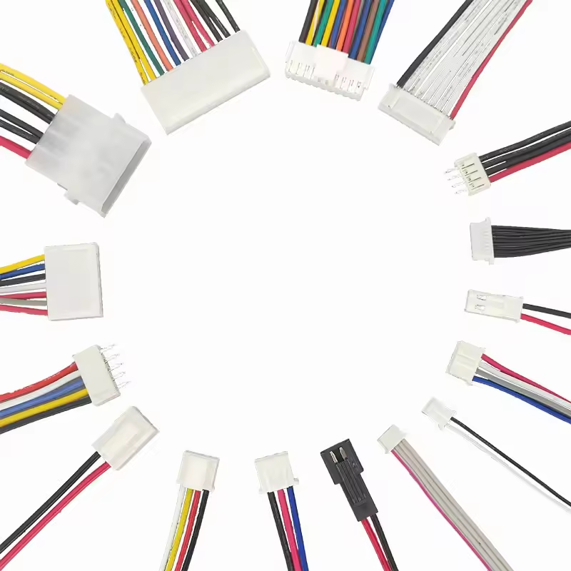
Most electrical system failures originate at the interconnects. The wire itself rarely fails under normal conditions. Connectors bear the brunt of mechanical stress, thermal cycling, and environmental exposure. Specifying the wrong connector creates cascading problems across your production cycle. You face immediate assembly bottlenecks on the production floor. Scrap rates spike during terminal crimping due to mismatched tooling. In the field, vibration and moisture cause intermittent faults. These failures inevitably lead to costly product recalls and damaged reputations.
This guide provides a technical framework for evaluating and selecting interconnects. You will learn how to balance electrical power demands, data signal integrity, and environmental durability. We focus heavily on manufacturability and assembly efficiency. Reliable production requires components designed for repeatable, error-free installation. Smart component selection eliminates manufacturing hurdles before they reach the assembly line.
Application Dictates Specification: Connector selection must begin with environmental realities (IP rating, vibration, temperature) before electrical load.
Assembly Dictates Yield: The best connector will fail if the manufacturer lacks the precise crimp tooling, step-by-step assembly protocols, and quality control processes (IPC/WHMA-A-620 standards).
The Role of Connectors in Wiring Harness Reliability
Defining Success Criteria for Your Assembly
Success requires clear baseline metrics established early in the design phase. A reliable harness achieves zero-defect mating during installation. It sustains electrical continuity under peak loads without thermal degradation. It also guarantees repeatable assembly times for production operators. You must frame the core problem before selecting components. Are you optimizing for tight space constraints inside consumer electronics? Do you need rugged components for harsh outdoor environments? Perhaps your priority is high-volume automated assembly. Each scenario demands a different interconnect strategy. Engineers often over-specify electrical ratings while ignoring mechanical realities. A balanced approach ensures both field performance and factory manufacturability.
To establish a baseline for success, you should track these specific metrics during prototyping:
First-pass yield during the crimping and insertion phases.
Mating force required by the operator on the assembly line.
Voltage drop across the connection under maximum continuous load.
Retention force of the terminal inside the plastic housing.
Common Points of Failure at the Connector Level
Connectors fail in predictable, measurable ways. Terminal back-out occurs when pins fail to lock fully into the plastic housing. Fretting corrosion degrades contacts exposed to continuous micro-vibrations. Inadequate strain relief transfers mechanical tension directly to the fragile crimp joint. Improper crimp height compromises both electrical resistance and mechanical pull strength. These realistic failure modes directly impact the end-user experience. Equipment downtime frustrates customers and damages brand loyalty. Preventing these issues requires rigorous component selection and validated assembly protocols.
Failure Mode
Root Cause
Prevention Strategy
Terminal Back-Out
Incomplete insertion or broken locking tangs.
Specify housings with Terminal Position Assurance (TPA).
Fretting Corrosion
Micro-vibration wearing away tin plating.
Use gold plating or apply dielectric grease.
Crimp Failure
Incorrect applicator tooling or worn anvils.
Implement automated crimp force monitoring.
Insulation Damage
Aggressive wire routing or lack of strain relief.
Add mechanical backshells or overmolding.
Evaluating Connector Wiring Harness Categories
Wire-to-Wire vs. Wire-to-Board Applications
Your specific application dictates the structural requirements of the interconnect. Wire-to-wire applications join two free-hanging cables. These inline connections endure significant handling and mechanical stress during installation. They require robust locking mechanisms to prevent accidental disconnection. Wire-to-board applications terminate a cable directly to a printed circuit board. These headers endure less movement but require precise alignment and strain relief. Locking mechanisms differ significantly between the two styles. Friction locks rely on tight plastic tolerances to hold components together. They suit low-vibration, internal enclosures. Positive latches provide an audible click and a physical mechanical interlock. You should specify positive latches for any application facing vibration or tension. Choosing the correct connector wiring harness category prevents premature field failures.
Sealed vs. Unsealed Connectors
Environmental protection requires careful evaluation of operating conditions. You must weigh the mechanical trade-offs between sealed and unsealed components. Sealed units utilize silicone wire seals and interfacial gaskets to block moisture and dust. They easily achieve IP67 or higher ratings. However, they consume more physical space and require higher mating forces to compress the internal seals. Unsealed units offer high pin density in compact spaces. They require lower mating force, which reduces operator fatigue during assembly. You should restrict unsealed components to strictly indoor, climate-controlled enclosures.
Feature
Sealed Connectors
Unsealed Connectors
Protection Level
Blocks moisture, dust, and chemical ingress (IP67+).
Minimal protection against environmental factors (IP20).
Components
Utilizes silicone wire seals and interfacial gaskets.
Bare plastic housings and exposed metal terminals.
Industry-Standard Connector Profiles for Specific Applications
JST MOLEX Wiring Harness Connectors
Standardized brands dominate signal routing and low-to-medium power applications. A JST MOLEX wiring harness provides proven reliability across diverse manufacturing sectors. These profiles excel in consumer electronics, internal appliance wiring, and automotive cabin controls. They offer tight-pitch configurations specifically designed for space-constrained PCB layouts. Common pitches include 1.25mm, 2.0mm, and 3.0mm spacing. Engineers must pay strict attention to component matching during specification. You must match the exact terminal series to the corresponding plastic housing. Mixing incompatible terminals causes micro-fretting and intermittent electrical continuity. Relying on established manufacturer families ensures consistent tooling availability globally. It also simplifies supply chain procurement during high-volume production runs.
M12 Connector Wiring Harness Applications
Industrial environments demand specialized ruggedness and reliable data transmission. The M12 standard dominates industrial automation, robotics, and remote sensor networks. Specifying an M12 connector wiring harness guarantees robust environmental protection. These standardized circular connectors feature secure threaded locking mechanisms. They easily achieve IP67 or IP68 ratings against water submersion and fine dust. The threaded coupling physically prevents disconnection under heavy machine vibration. M12 profiles support both power delivery and high-speed industrial data protocols. You select different coding styles based on the application. A-coded handles standard sensors and DC power. D-coded manages 100 Mbit Ethernet. X-coded supports Gigabit Ethernet for high-bandwidth vision systems. Their standardized form factor allows seamless integration across different equipment manufacturers.
Heavy-Duty and Automotive Profiles
Extreme environments destroy standard commercial interconnects rapidly. Applications facing severe vibration, thermal shock, and fluid exposure require heavy-duty solutions. Brands like Deutsch and Ampseal set the benchmark for these harsh conditions. They feature thick thermoplastic housings and robust, multi-ribbed silicone seals. Secondary locking mechanisms are absolutely critical for these environments. Terminal Position Assurance (TPA) locks ensure pins remain fully seated inside the housing cavity. TPA prevents terminal back-out during extreme thermal cycling and physical shock. Connector Position Assurance (CPA) locks prevent the two housing halves from separating accidentally. These features are mandatory for sensitive automotive applications. Camshaft, crankshaft, and driveshaft speed sensors rely entirely on these secondary locks for continuous, error-free operation.
Technical Evaluation Dimensions for Harness Connectors
Signal Integrity vs. Power Transmission
Power delivery and data transmission require entirely different evaluation criteria. High-current power delivery demands large contact surface areas. You must manage heat dissipation actively and minimize voltage drop across the connection. Sensitive, high-speed data signals require strict impedance control. Data-heavy applications demand specialized shielding to block electromagnetic interference. You cannot route high-speed data through standard power pins without risking severe signal degradation. Engineers must separate power and signal lines physically. Alternatively, you can specify hybrid connectors designed explicitly for mixed layouts. These hybrids isolate the power contacts from the shielded data lines within the same housing.
Electrical and Thermal Specifications
Current rating is never a static, absolute number. You must evaluate derating curves based on pin density and ambient operating temperature. A single isolated pin might carry 10 amps safely. A fully loaded 12-pin housing might only support 5 amps per pin due to internal heat accumulation. Voltage limits dictate the required physical spacing between contacts to prevent arcing. You must also verify AWG compatibility for the chosen terminal series. Contact resistance generates heat during continuous operation. Unmanaged temperature rise melts plastic housings and causes catastrophic system failure.
Wire Gauge (AWG)
Typical Max Current (Amps)
Common Application
24 AWG
2.0 - 3.0 A
Low-level sensors, data signals.
20 AWG
5.0 - 7.0 A
Internal device wiring, LED lighting.
16 AWG
10.0 - 15.0 A
Automotive accessories, industrial controls.
12 AWG
20.0 - 25.0 A
Main power distribution, heavy motors.
Material Selection: Housings and Contact Plating
Operating environments dictate housing material selection directly. Standard Nylon 6/6 suits most indoor, climate-controlled applications perfectly. High-temperature environments require advanced polymers like Polybutylene Terephthalate or Liquid Crystal Polymer. These materials withstand reflow soldering temperatures and severe engine bay heat. Terminal plating options drastically affect performance. Specify gold plating for low-current data signals and sensors. Gold resists oxidation entirely and supports high mating cycles in corrosive environments. Specify tin plating for higher current, static connections. Tin performs well for power delivery but suffers from fretting corrosion under continuous vibration. Never mate a gold terminal to a tin terminal. The dissimilar metals cause rapid galvanic corrosion.
Mechanical Durability and Mating Cycles
Mechanical specifications determine the long-term physical reliability of the assembly. Retention force measures how securely the housing holds the crimped terminal. Insertion and extraction forces dictate operator fatigue during manual assembly. You must assess the maximum number of mating cycles before plating degradation occurs. Standard tin contacts might survive only 25 cycles before exposing base metal. Premium gold contacts can easily exceed 500 cycles. Keying and polarization features are absolute necessities for production. They physically prevent operators from mis-mating connectors on a fast-paced assembly line. Color-coding housings further reduces assembly errors when multiple identical connectors exist on the same harness.
Regulatory Compliance and Standards
Global hardware distribution requires strict regulatory compliance from day one. You must map out essential certifications early in the design phase. UL94V-0 ratings verify flammability resistance for plastic housings. RoHS and REACH compliance ensures materials lack restricted hazardous substances. Furthermore, component selection must align with established manufacturing standards. Specify components compatible with IPC/WHMA-A-620 guidelines. This standard governs cable and wire harness assembly criteria globally. It defines acceptable crimp heights, insulation clearances, and routing practices. Compliance guarantees consistent, measurable quality across different contract manufacturing facilities.
Best Practices for the Wire Harness Assembly Process
Design for Manufacturability (DFM) and Documentation
Reliable assembly begins with comprehensive, unambiguous design documentation. You must generate precise schematics, detailed wire lists, and strict tolerance specifications early in the lifecycle. Ambiguity in documentation leads directly to manufacturing errors on the floor. A proper wire list includes from/to destinations, wire colors, AWG sizes, and specific terminal part numbers. Early Design for Manufacturability reviews are critical for success. They bridge the gap between engineering intent and production reality. DFM reviews identify impossible routing paths, incompatible components, and tooling constraints. Catching these issues early prevents tooling changes and delays later in production.
The Step-by-Step Manufacturing Workflow
The core assembly process follows a strict, repeatable workflow. It begins with automated wire cutting and stripping. Precision machines ensure consistent strip lengths without nicking internal conductor strands. Next comes terminal crimping. This step requires exact applicator tooling and continuous force monitoring. The crimp must capture both the bare conductor and the wire insulation perfectly. Operators then perform precise connector insertion, listening for the audible click of the locking tang. Final routing and bundling secure the completed assembly using zip ties, heat shrink, or braided sleeving. Standardizing connectors across your product line streamlines this entire workflow. It reduces tooling changeovers and minimizes operator error significantly.
Performance Trade-offs in Connector Selection
Off-the-Shelf vs. Custom Tooling
Proprietary connectors carry massive impacts on production timelines. Custom designs require expensive injection molds and dedicated applicator tooling. These upfront requirements rarely justify the perceived design benefits for most applications. Leveraging Commercial Off-The-Shelf components eliminates custom mold requirements entirely. Standard parts utilize existing, proven tooling infrastructure. Contract manufacturers already own the applicators for standard profiles. This approach drastically reduces initial capital expenditure and accelerates your time to market. It also ensures you can switch manufacturing partners without transferring proprietary tooling.
Supply Chain Availability and Lead Times
Component shortages remain a constant reality in modern manufacturing. Relying on a single, highly specialized connector introduces severe supply chain risk. You must develop strategies to mitigate unexpected production halts. Identify cross-references and drop-in replacements during the initial design phase. Validate alternative brands that share identical footprints and performance specifications. Proactive cross-referencing ensures production continues smoothly even when primary suppliers face extended lead times. Document these approved alternates directly on your engineering drawings to empower your purchasing team.
Implementation Risks and Assembly Mitigation
Crimping Tolerances and Tooling Calibration
A connector is only as reliable as its crimp. Poor crimping causes the vast majority of harness failures. Hand tools introduce human error and inconsistent application pressure. They suit prototyping but fail completely in volume production. Automated presses provide repeatable, microscopic accuracy. They utilize integrated crimp force monitors to analyze every single termination in real-time. These monitors detect missing wire strands or improper insulation placement instantly. Strict tooling calibration schedules maintain these tight crimping tolerances over millions of cycles. You must measure crimp height and width regularly using specialized micrometers.
Strain Relief and Overmolding Considerations
Mechanical stress destroys the connector-to-wire junction rapidly. You must evaluate methods to protect this vulnerable transition area. Basic heat shrink tubing offers minimal structural support and moderate abrasion resistance. Mechanical backshells provide superior strain relief and secure cable routing for heavy cables. They clamp down on the outer cable jacket, isolating the internal wires from pulling forces. Custom injection overmolding delivers the ultimate physical protection. Overmolding encapsulates the entire junction in rugged thermoplastic. It creates a completely waterproof seal and impenetrable strain relief.
Testing Protocols for Quality Assurance
Quality assurance demands a mandatory, rigorous testing regimen. Visual inspection alone cannot verify a reliable wiring harness. Pull-force testing verifies the mechanical strength of the crimp joint against strict standards. Point-to-point continuity testing ensures correct pinout configurations and identifies hidden open circuits. Hi-Pot testing applies high voltage to verify dielectric withstand capabilities. It detects microscopic insulation flaws and prevents dangerous short circuits in the field. Automated test boards check for miswires, shorts, and intermittent connections simultaneously.
Request a comprehensive Design for Manufacturability review with your assembly partner to identify tooling constraints.
Order physical prototypes to verify mating forces, cable routing, and spatial constraints within your enclosure.
Audit your contract manufacturer to ensure they utilize automated crimping presses equipped with real-time force monitoring.
Establish a clear testing protocol that includes mandatory pull-force, continuity, and Hi-Pot testing before full production begins.
FAQ
Q: What is the difference between a cable assembly and a wiring harness?
A: A cable assembly typically features a single cable with connectors on each end, often covered by a heavy outer jacket for external use. A wiring harness is a complex grouping of multiple individual wires and breakouts, bound together by tape or loom, designed to route power and signals internally within a device or vehicle.
Q: How do I choose between gold and tin terminal plating?
A: Choose gold plating for low-current data signals, sensors, and applications requiring high mating cycles or operating in corrosive environments. Gold prevents oxidation. Choose tin plating for higher current power delivery and static connections that experience minimal vibration, as tin is more cost-effective but susceptible to fretting corrosion.
Q: What causes terminal back-out in harness connectors?
A: Terminal back-out happens when a crimped pin is not fully seated and locked into the plastic housing cavity. It is caused by operator error during insertion, damaged locking tangs, or severe cable tension. Using connectors with Terminal Position Assurance (TPA) secondary locks prevents this failure.
Q: Why is Terminal Position Assurance (TPA) necessary?
A: TPA is a secondary plastic locking mechanism inserted into the connector housing. It physically blocks terminals from backing out due to vibration, thermal expansion, or cable strain. TPA is mandatory in automotive, heavy machinery, and harsh environment applications where connection failure causes critical system downtime.
Q: How does wire gauge affect connector selection?
A: Every connector terminal series is engineered for a specific American Wire Gauge (AWG) range. Using a wire too thick prevents the terminal from fitting into the housing. Using a wire too thin results in a loose crimp, causing high electrical resistance, heat generation, and eventual mechanical failure.
Q: What is the standard testing method for crimp quality?
A: The primary mechanical test is the pull-force test, which measures the exact force required to pull the wire out of the crimped terminal. Electrically, crimp quality is verified by measuring contact resistance and utilizing crimp force monitors on automated presses to detect missing strands during production.